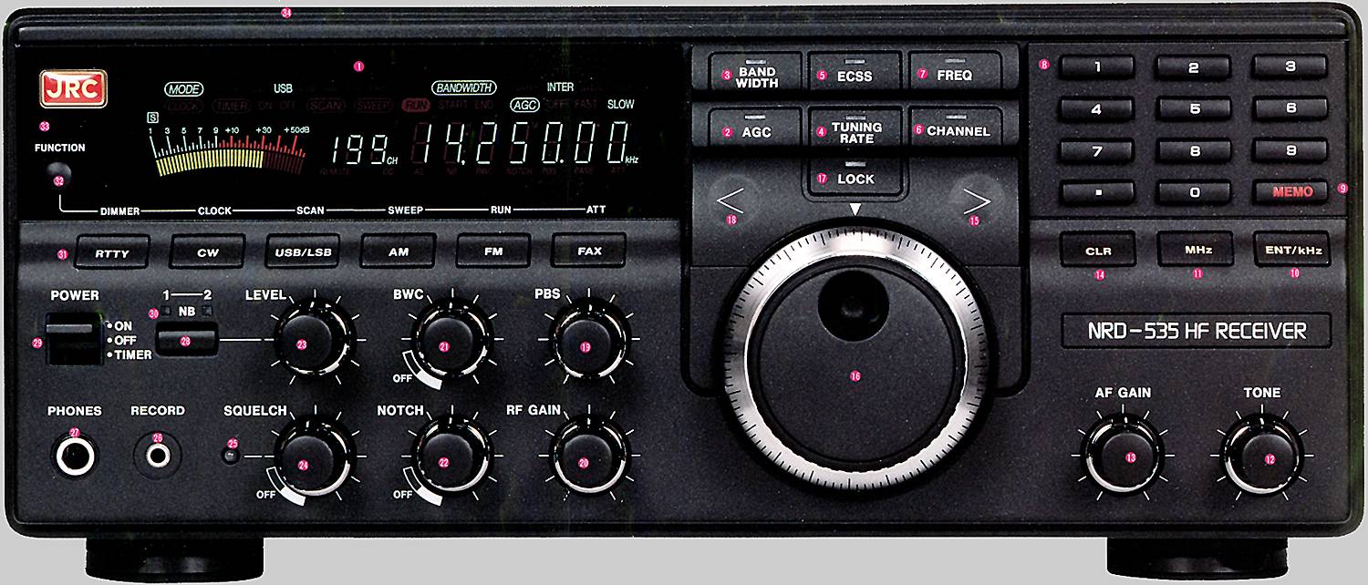
JRC NRD-535 Controls and Features| 1 | Vacuum Fluorescent Display | 2 | AGC Switch with LED | 3 | Bandwidth Switch with LED |
| 4 | Tuning Rate Switch with LED | 5 | ECSS (Exalted Carrier Selectable Sideband) Switch with LED | 6 | Channel Switch with LED |
| 7 | Frequency Switch with LED | 8 | Numerical Keys | 9 | Memory Switch |
| 10 | Frequency Entry Switch | 11 | MHz Switch | 12 | Tone Control |
| 13 | AF Gain Control | 14 | Clear Switch | 15 | Right / Up Switch |
| 16 | Main Tuning Control | 17 | Lock Switch with LED | 18 | Left / Down Switch |
| 19 | PBS (Pass Band Shift) Control | 20 | RF Gain Control | 21 | BWC (Band Width Control) |
| 22 | Notch Control | 23 | Noise Blanker Level Control | 24 | Squelch Level Control |
| 25 | Squelch Closed LED | 26 | Record Jack | 27 | Headphone Jack |
| 28 | Noise Blanker Switch | 29 | Power On / Off and Timer Switch | 30 | Noise Blanker Selection LEDs |
| 31 | Receive Mode Selection Switches | 32 | Function Switches | 33 | Function Switched Indicator LED |
| | 34 | Internal Speaker (Top Panel) | | |
 Back to JRC NRD-535 Information